Friday, July 11, 2014

What is Nodal Analysis

Nodal Analysis provide a general procedure for analyzing circuits using node voltages as the circuit variables.

Steps to Determine Node Voltages:
1. Select a node as the reference node, Assign voltages v1, v2, . . . . . , 
vn-1 to the remaining n-1 nodes. The voltages are referenced with respect to the reference node.

2.Apply KCL to each of the n-1 non-reference nodes. Use Ohm’s law to express currents in terms of node voltages.

3. Solve the resulting simultaneous equations to obtain the unknown node voltages.


Nodal Analysis with Voltage Sources

Case 1: If the voltage source (dependent or independent) is connected between two non-reference nodes, the two non-reference nodes form a generalized node or super node, we apply both KCL and KVL to determine the node voltages.
Case 2: if a voltage source is connected between the reference node and a non-reference node, we simply set the voltage at the non-reference node equal to the voltage of the voltage source.

~ In every different kind of circuits when in comes to analyzing and solving, we should practice the steps of determining the node voltages and must able to observe if what kind of case the circuit is.

To understand more, watch this video :)


There are some instances that a voltage source is in between to the two non-reference node in a loop, that's SUPERNODE.
In circuit theo, a super-node is a theoretical construct that can be used to solve a circuit. This is done by viewing a voltage source on a wire as a point source voltage in relation to other point voltages located at various nodes in the circuit, relative to a ground node assigned a zero or negative charge.


The application that needs to study:
- KVL/KCL (on my CHAPTER 2 blog)
- Cramer's rule

Our chapter 2 journey in Electric circuit!

There are some instances that it's hard for us to solve/interpret a circuit especially when your knowledge is just revolves around Ohm's Law because the circuit have it's different behavior that needs to analyze. But thanks to Gustav Robert Kirchhoff for having the Kirchhoff's Law(KCL & KVL). But for now, let me introduce to you the voltage division and current division.

Anyway, voltage and current division allow us to simplify the task of analyzing a circuit. :)

Voltage division allows us to calculate what fraction of the total voltage across the series string of resistors is dropped across any one resistor. 


 The figure above is a sample of a circuit that can be defined by using voltage divider, the formula of that is:


 So, you can solve already the simple circuit that I've shown to you by having that formula. :)

Next,
Current division, it allows us to determine how the current flowing into a node is split between various parallel resistors.

Observe this circuit,
In this circuit, the resistors are in parallel connection. So we can apply here the current divider because that's what it takes. Here is the formula:


Let's go back to KVL and KCL.
 
 Kirchhoff's voltage law, states that the algebraic sum of all the voltages around a closed circuit equals zero. 
 Another way of stating kirchhoff's voltage law is, the sum of all the voltage drops in a closed circuit will equal the voltage source.


 The sample figure that I've shown to you as KVL sample, there are four voltage drops and one voltage source in the circuit. If the voltages are summed around the circuit as shown, they equal zero.

The voltage source has a sign opposite that of the voltage drops. Therefore, the algebraic sum equals zero.  In another way, the sum of voltage drops will equal the voltage source. 

These two formulas are just the same thing and are equivalent ways of expressing Kirchhoff's Voltage Law. :)


Kirchhoff's current law, states that the algebraic sum of all the currents entering and leaving a node is equal to zero. Another way of stating the KCL is that the total current flowing into a node is equal to the sum of the current flowing out of that node.

Let me tell you something about a Node :)
A node is defined as any point of a circuit at which two or more current paths meet. In parallel circuit, the node is where the parallel branches of the circuit connect.
Then what is a branch? 
A branch  represents a single element such as a voltage source or a resistor that can be found in a loop.
Do you know what is a loop?
Anyway, a loop is any closed path in a circuit. So anything that is a closed path in a circuit is a loop.

To be clearer to you about the KCL, let just watch this video for a further explanation.  :) 


I hope you've learn a lot about it as what I have learn too. Some information that was written/viewed, data and pictures are came from the internet/book, and some are came from my own learning and understanding. Thank you :)

TAKE NOTE: "you will gradually know the characteristics of a circuit by just keep on solving any behavior of a different circuit that can be seen in the book of Alexander Sadiku the author, named Fundamentals of Electric Circuit(fourth edition). Just enjoy solving and you'll find it easier."

See you on the next blog!

Saturday, July 5, 2014

The importance of OHM's LAW in Electric circuit

Ohm's Law defines the relationship among three fundamental quantities which are the current, voltage, and resistance Current is directly proportional to voltage and inversely proportional to resistance. 

This may expressed as: V=I/R 

I = current in Amperes 

V = voltage in volts 

R = resistance in ohms 


 Few days ago, we discuss how the three fundamental quantities are being applied in a circuit.

The current flow in an electric circuit can be varied by changing either the voltage applied to circuit or the resistance in the circuit. The current changes in exact proportions to the change in the voltage or resistance. If the voltage is increased, the current also increases. If the voltage is decreased, the current also decreases. On the other hand, if the resistance is increased, the current decreases. 


 To be continued! :)

See you on the next topic that I might gonna share to you, and its all about KVL/KCL

Friday, June 27, 2014

Knowing the basic laboratory equipments and componets


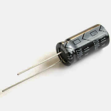
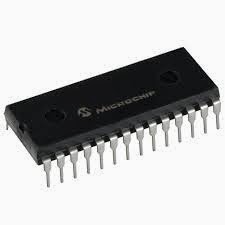
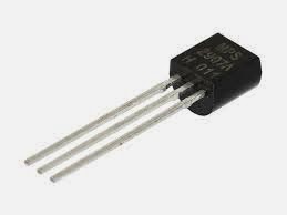
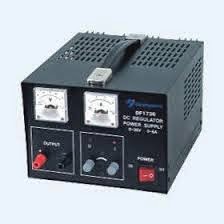
There are common equipments and components in the laboratory in circuits 1. We should familiarize all of them so that we'll know their uses, capacity and what are the purpose of these objects. We are given 10 elements named Capacitor, IC, Transistor, Inductor, Resistor, Digital Multimeter, Power supply and Current source.
  • A capacitor stores electric charge and is mainly used with resistors in timing circuits. It also acts as a filter by passing alternating current (AC), and blocking direct current (DC). The charge of a capacitor is measured in units called Farads. 
  • An integrated circuit (IC), sometimes called a chip or microchip, is a semiconductor wafer on which thousands or millions of tiny resistors, capacitors, and transistors are fabricated. An IC can function as an amplifier, oscillator, timer, counter, computer memory, or microprocessor. A particular IC is categorized as either linear (analog) or digital, depending on its intended application. 
  •  A transistor is a semiconductor device used to amplify and switch electronic signals and electrical power.
  •  An inductor is a passive electronic component that stores energy in the form of a magnetic field. In its simplest form, an inductor consists of a wire loop or coil.
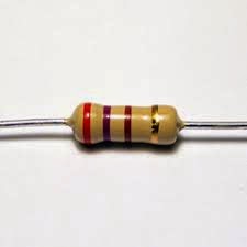
  •  Resistor is an electrical component that reduces the electric current.
  •  A multimeter is used to make various electrical measurements, such as AC and DC voltage, AC and DC current, and resistance.
  • A power supply is an electronic device that supplies electric power to an electrical load.   

CAPACITOR

IC (INTEGRATED CIRCUIT)

TRANSISTOR

DIGITAL MULTIMETER


INDUCTOR

POWER SUPPLY

RESISTOR


We usually see those instruments everywhere, but we didn't know their importance in our life. The different function they have could help a lot to us as a human being but thanks to those who invented them. I think by knowing those objects, we can use it now in accordance to its purpose and we need more experience through it so we are flexible where to put them and what it could bring about. 
  
 TO BE CONTINUED! :)

Saturday, June 21, 2014

Its about Charge and current with respect to time

Last time, we have our quiz and the quiz was all about the figure shown above. We, the student must determine the total charge that passed through the element of (a)t=1s, (b)t=3s, and (c)t=5s. *I'll just show you how this problem was being solve later* Actually, before we come to this kind of problem, we already encounter the same as this but different form, given and problem. When we go through to this, I've come to realize that our past math lessons are being applied to this course in order to solve it, like for example the "slope intercept form" which was taken from our college algebra and many others. . .
 The solution:


First week! First topic!

As our journey with Electric Circuit course starts, we really expect that this subject is not easy as its prerequisite. We start discussing about POWER. We all know that Power is the time rate of expending or absorbing energy, measured by watts (W). And so there was these two kinds of power which is the Negative and the Positive power, but it’s just now I know that the positive power are elements absorbs power and the negative one are the elements supplies power. Anyway, the equation in getting or solving the wattage is P=IV, so it’s just a matter between voltage and current. Then, we talks about the necessary “simple principles” of the circuit that needs to be captured by us so that we have something to look for or hold on when we’re already on the high level in acquiring knowledge, by that we are capable in understanding the problems that we will encounter soon because we already have the background regarding to this subject. We also talk about the three major parts of electric circuit and those are the Power supply/source, Conductor and Load. The reminders that I've learn: -how to keep yourself safe when it comes to handling the electricity -the outlets of electricity must be clean and not dusty -the current will flow to any conductor even to a person's body